| “This site contains affiliate links for which OEMDTC may be compensated” |
NHTSA Campaign Number: 17V040
Manufacturer Nissan North America, Inc.
Components LATCHES/LOCKS/LINKAGES
Potential Number of Units Affected 341,005
Rear Door may Open when Window is Lowered
If the rear passenger doors inadvertently open while the vehicle is in motion, it may increase the risk of injury to the rear passengers.
Summary
Nissan North America, Inc. (Nissan
 ) is recalling certain 2015-2017 Altima vehicles.
The rear door latch/lock cable on the vehicles may have been improperly routed.
As a result, lowering a rear window may inadvertently cause that door to unlatch and open.
Remedy
Nissan will notify owners, and dealers will correct the rear door latch/lock cable routing, free of charge.
The recall began on February 16, 2017.
Owners may contact Nissan customer service at 1-800-647-7261.
Notes
Owners may also contact the National Highway Traffic Safety Administration Vehicle Safety Hotline at 1-888-327-4236 (TTY 1-800-424-9153), or go to www.safercar.gov.
Check if your Nissan has a Recall
| Reference: | Date: |
| NTB17-012 | February 2, 2017 |
VOLUNTARY SAFETY RECALL CAMPAIGN
2015-2017 ALTIMA; REAR DOOR
SEALING SCREEN/VAPOR BARRIER
CAMPAIGN ID #: PC540
APPLIED VEHICLE: 2015-2017 Altima (L33)
INTRODUCTION
Nissan is conducting a voluntary safety recall campaign on certain specific 2015-2017 model year Altima vehicles to inspect both rear door vapor barriers. Depending on inspection results, the vapor barriers will be adjusted or replaced. If replaced, the inside cables and handles will be inspected and replaced as needed. This service will be performed at no charge for parts or labor.
IDENTIFICATION NUMBER
Nissan has assigned identification number PC540 to this campaign. This number must appear on all communications and documentation of any nature dealing with this campaign.
DEALER RESPONSIBILITY
It is the dealer’s responsibility to check Service COMM for the campaign status on each vehicle falling within the range of this voluntary safety recall campaign which for any reason enters the service department. This includes vehicles purchased from private parties or presented by transient (tourist) owners and vehicles in a dealer’s inventory. Federal law requires that new vehicles in dealer inventory which are the subject of a safety recall must be corrected prior to sale. Failure to do so can result in civil penalties by the National Highway Traffic Safety Administration. While federal law applies only to new vehicles, Nissan strongly encourages dealers to correct any used vehicles in their inventory before they are retailed.
REPAIR FLOW CHART
 Loading...
SERVICE PROCEDURE
Inspect Vapor Barrier
NOTE: Perform SERVICE PROCEDURE on both rear doors.
- Verify the ignition is OFF and the rear door window is in the UP (closed) position.
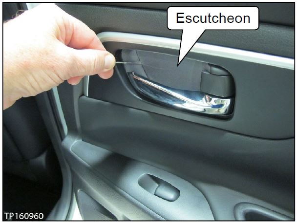
- Remove the inside door handle escutcheon with a suitable tool (see Figure 1).
Figure 1
CAUTION:
- Do not scratch door components during disassembly.
- Be careful when removing the Figure 1 escutcheon. This part will be reinstalled during reassembly.
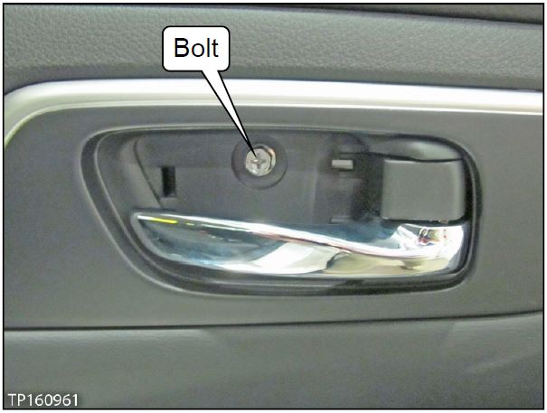
- Remove the inside handle bolt (see Figure 2).
Figure 2
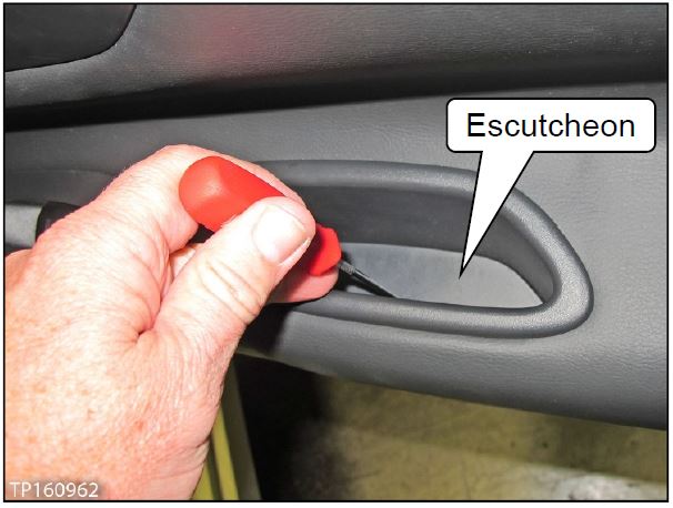
- Remove the door tray escutcheon using a suitable tool (see Figure 3).
Figure 3
CAUTION: Do not scratch door components during disassembly.
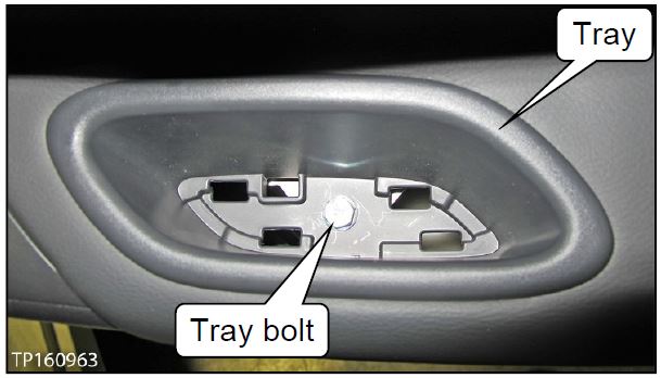
- Remove the tray bolt and tray (see Figure 4).
Figure 4
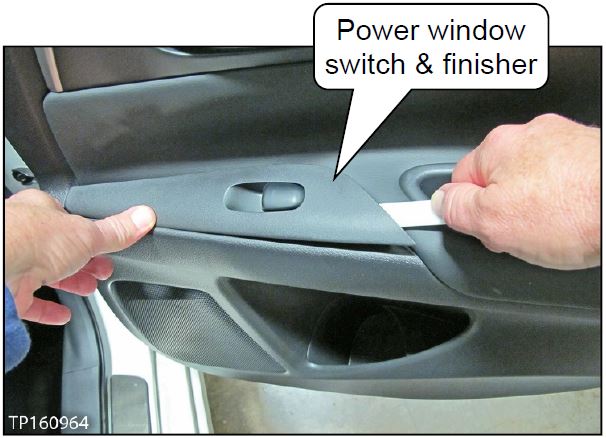
- Remove the power window switch with finisher.
a. Using a suitable tool, start lifting at the rear, pull upward, and then remove (see Figure 5).
b. Disconnect the harness connector.
Figure 5
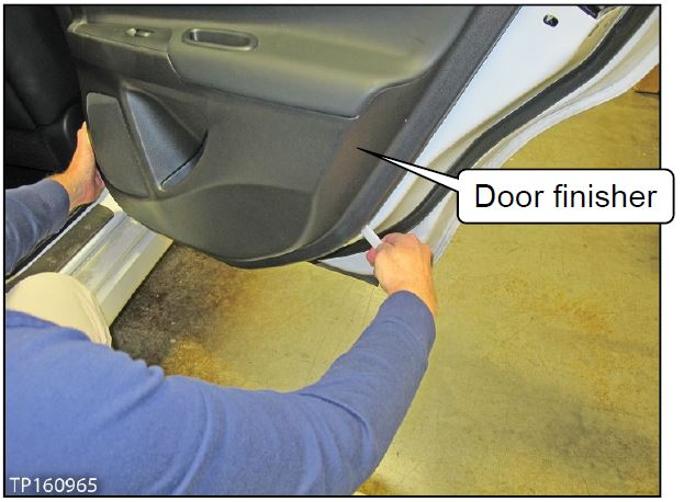
- Remove the door finisher.
a. Unfasten the finisher clips using a suitable tool (see Figure 6).
Figure 6
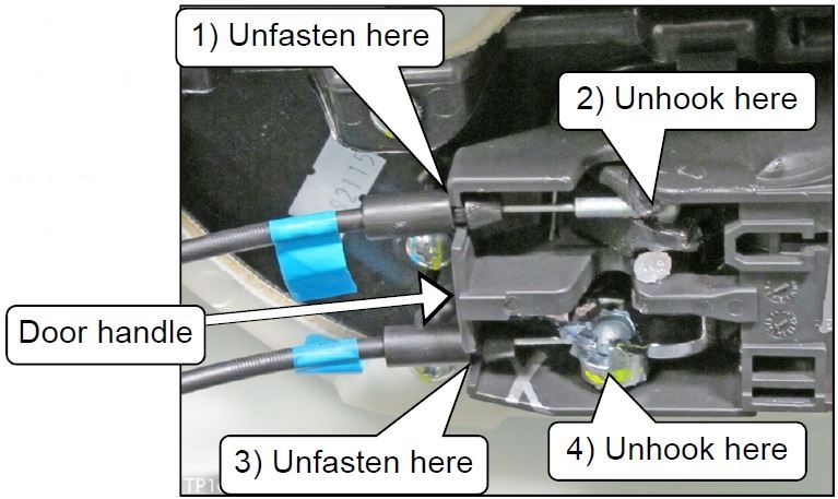
b. Unfasten both cables from the inside door handle, one cable at a time (see Figure 7).
Figure 7
NOTE: Place the door finisher where it will not be soiled or damaged.
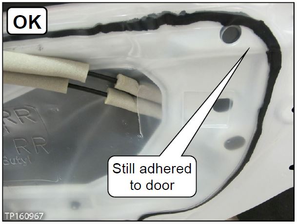
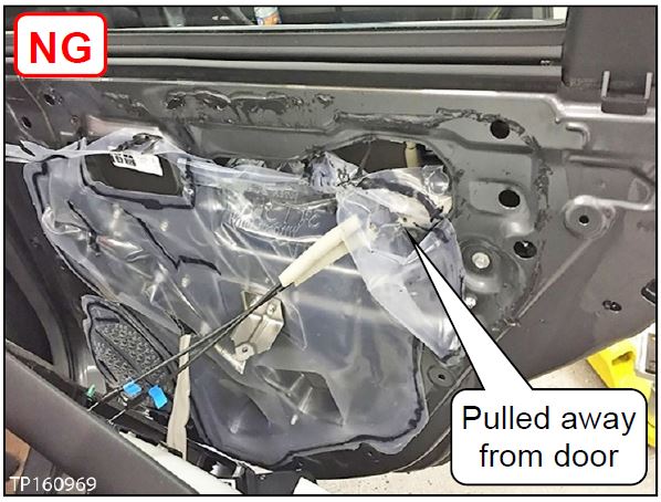
- Inspect the upper right portion of the vapor barrier.
a. If the vapor barrier’s condition is similar to the one in Figure 8, go to page 6, Vapor Barrier – Adjustment.
Figure 8
b. If the vapor barrier’s condition is similar to the one in Figure 9, go to page 8, Inspect Cables and Inside Handle, and Replace Vapor Barrier.
Vapor Barrier – Adjustment
NOTE: Vapor barrier adjustment is performed only when the vapor barrier passes inspection.
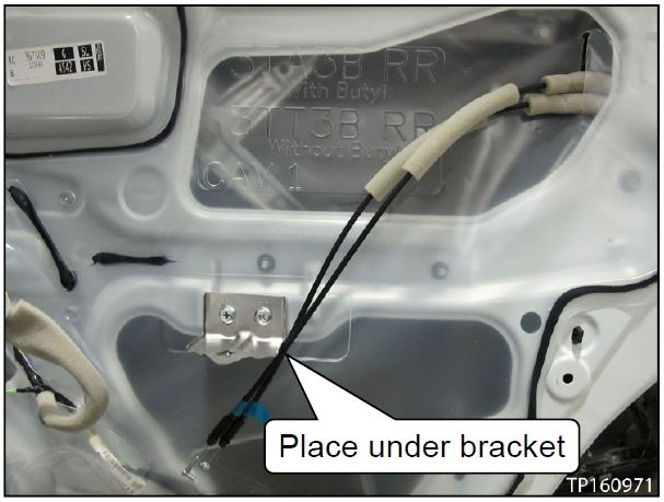
- Gently place the cables out of the way under the door finisher bracket (see Figure 10).
Figure 10
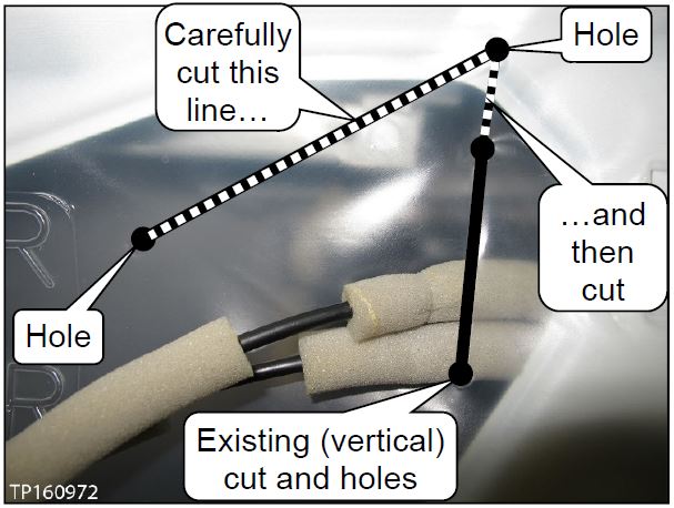
- Carefully cut the line (see Figure 11) in the vapor barrier from hole to hole with a sharp suitable tool.
Figure 11
NOTE: This line is stamped into the vapor barrier with a hole at each end.
CAUTION:
- Do NOT cut past the stamped holes.
- Be careful when cutting near the cables.
- After completing step 2, make a second cut from hole to hole where shown in Figure 11.
- The second cut will create a flap.
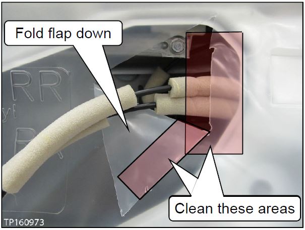
- Fold the flap down (see Figure 12).
- Clean the back side of the vapor barrier where shown in Figure 12.
- Use Alcohol Prep Pad J-50397-18 or equivalent.
- Alcohol Prep Pad J-50397-18 is stored in Squeak & Rattle Repair Kit J-50397.
Figure 12
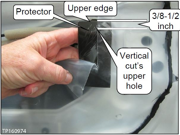
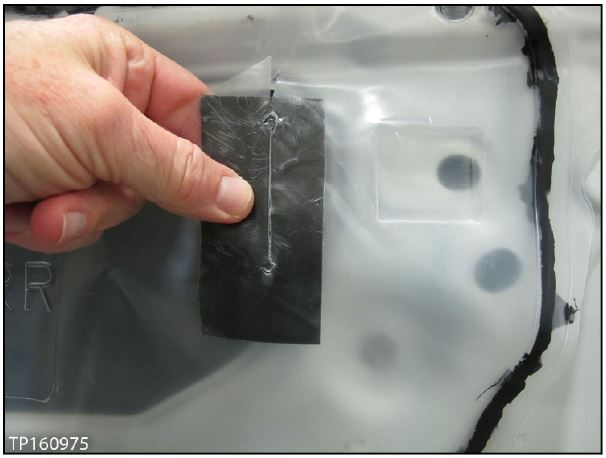
- Apply one (1) piece of Protector (tape) where shown in Figure 13 and 14.
- Protector P/N: 24271-0Z000 (see PARTS INFORMATION).
a. Apply the tape’s sticky side on the area prepped in step 5 (see Figure 12).
b. Position the tape:
- Upper edge: 3/8 – 1/2 inch (10 – 13 mm) above the vertical cut’s upper hole (see Figure 13).
- Horizontally centered on the vertical cut.
Figure 13
c. Firmly press the tape to the vapor barrier.
d. Raise the flap and press it to the tape.
- Make sure the whole surface of the tape is adhered to the flap and vapor barrier with no gaps in the vertical cut (see Figure 14).
IMPORTANT: The tape MUST be properly adhered to the backside of the vapor barrier and flap.
Figure 14
- Reassemble the door in reverse order of disassembly.
- See page 10 for proper cable routing.
- After the repair is complete, close the door firmly 10 times, and then verify the power window, inside and outside door handle, and door lock knob operates normally.
- Visually inspect the door panel and all related components for damage.
If only one rear door has been completed, go back to page 3 and perform SERVICE PROCEDURE on the remaining rear door.
Inspect Cables and Inside Handle, and Replace Vapor Barrier
NOTE: It is not necessary to inspect the cables and inside door handle of a rear door if its vapor barrier passed inspection. Inspect these parts only if a vapor barrier fails inspection.
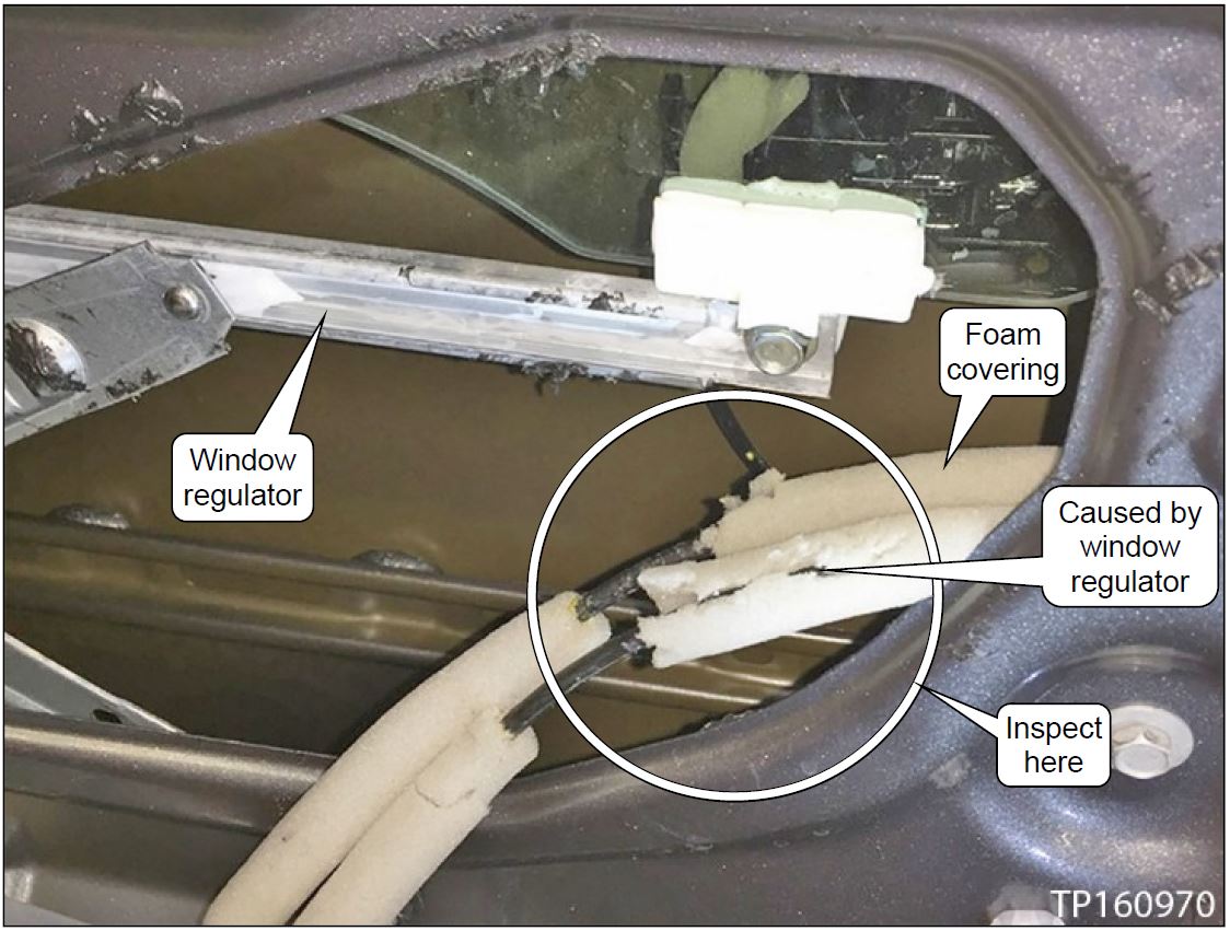
- Inspect the foam covering on the cables for damage (see example in Figure 15).
- Damage found: Replace the door lock assembly with cables.
- Refer to the ESM, section DLK-Door & Lock, door lock assembly with cables replacement.
- Skip to page 9, step 4.
- No damage found: Do not replace the door lock assembly with cables.
- Skip to page 9, step 7.
Figure 15
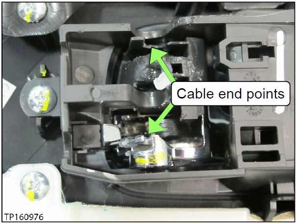
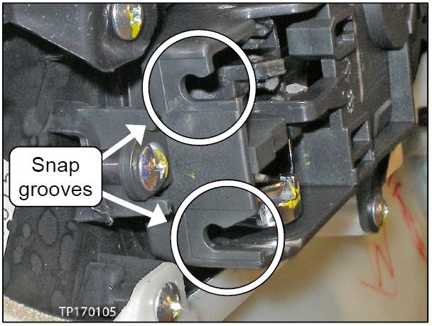
- Inspect the inside door handle snap grooves and cable end points for damage (see Figure 16 and 17).
NOTE: The inside door handle is fastened to the back side of the door finisher.
Figure 16
- Damage found: Replace the inside door handle.
- Refer to the ESM, section INT- Interior, for inside handle
- No damage found: Do not replace the inside door handle.
- Go to the next step.
Figure 17
- Replace the damaged vapor barrier.
NOTE: The replacement vapor barrier has the correct opening (cut) and does not need to be adjusted.
- Reassemble the door in reverse order of disassembly.
- See page 10 for proper cable routing.
- After the repair is complete, close the door firmly 10 times, and then verify the power window, inside and outside door handle, and door lock knob operates normally.
- Visually inspect the door panel and all related components for damage.
If only one door has been completed, go back to page 3 and perform SERVICE PROCEDURE on the remaining rear door.
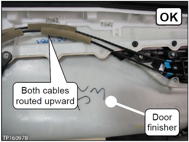
Cable Routing
Figure 18 shows proper routing of the cables.
Figure 18
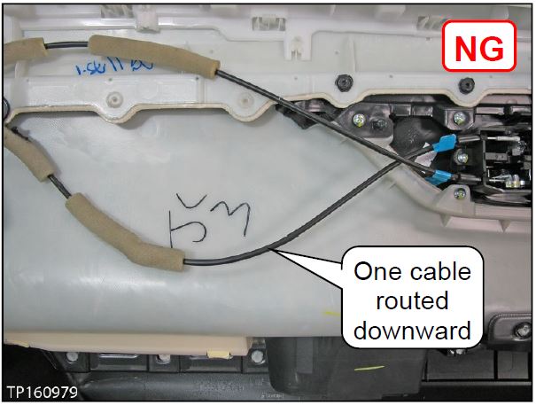
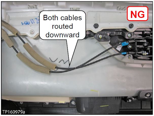
Figure 19 and 20 show incorrect routing of the cables.
Figure 19
Figure 20
NOTE: For better visibility, the vapor barrier is not installed in Figure 18, 19, and 20.
PARTS INFORMATION
| DESCRIPTION | PART NUMBER | QUANTITY |
| PROTECTOR (TAPE) | 24271-0Z000 | Up to 2; as needed |
CLAIMS INFORMATION
Submit a Campaign (CM) line claim using the following claims coding:
| CAMPAIGN (CM) ID # | DESCRIPTION | OP CODE | FRT |
| PC540 | Inspect/Repair Both Rear Doors * | PC5400 | 0.5 hrs. |
* Includes replacement of any vapor barriers and/or door handles and/or door lock and cable assemblies, if needed.
 Loading...
 Loading...
 Loading...
 Loading...
