
| Classification: | Reference: | Date: |
| FA21-006 | NTB21-061 | July 6, 2021 |
VOLUNTARY SAFETY RECALL CAMPAIGN
2021 GT-R; STEERING KNUCKLE
Check Service COMM or Dealer Business Systems (DBS) National Service History to confirm campaign eligibility.
INTRODUCTION
Nissan is conducting this voluntary safety recall campaign, on certain specific model year 2021 GT-R vehicles, to replace both front steering knuckles. This service will be performed at no charge to the customer for parts or labor.
IDENTIFICATION NUMBER
Nissan has assigned identification number R21A4 to this campaign. This number must appear on all communication and documentation of any nature dealing with this campaign.
DEALER RESPONSIBILITY
It is the dealer’s responsibility to check Service COMM or Dealer Business Systems (DBS) National Service History for the campaign status on each vehicle falling within the range of this voluntary safety recall which for any reason enters the service department. This includes vehicles purchased from private parties or presented by transient (tourist) owners and vehicles in a dealer’s inventory. Federal law requires that new vehicles in dealer inventory which are the subject of a safety recall must be corrected prior to sale. Failure to do so can result in civil penalties by the National Highway Traffic Safety Administration. While federal law applies only to new vehicles, Nissan strongly encourages dealers to correct any used vehicles in their inventory before they are retailed.
SERVICE PROCEDURE
WARNING
To avoid the risk of death or severe personal injury, do not reuse single use parts noted in this TSB. Reusing a single use part may induce risk that it, or the component that it secures, may become loose.
Remove The Steering Knuckle
- Place the vehicle on a lift and raise to a suitable height.
- If the vehicle is equipped with Nissan Carbon Ceramic Brakes (NCCB), install a disc rotor protector (SST: KV40109300) before removing the wheel and tire assemblies to protect the brake rotor from oils or foreign debris.
- If the vehicle is equipped with cast iron disc rotors, skip to step 3.
- Remove both front wheel and tire assemblies.
- Remove the front wheel speed sensor bolt from the steering knuckle (Figure 2) and the 3 speed sensor harness grommets from the brake hose bracket (Figure 2 and Figure 3).
- Position the wheel speed sensor and harness out of the way of the steering knuckle.
- Remove the 3 brake hose bracket bolts, and then remove the brake hose bracket from the steering knuckle.
- Remove the brake hose from the shock absorber.
HINT: Temporarily install and tighten a wheel nut to hold the brake rotor in place.
- Remove the 3 brake caliper mounting bolts and then remove the brake caliper from the steering knuckle (Figure 9 and Figure 10).
- Place the removed brake caliper on a suitable jack wrapped in cloth (Figure 10).
CAUTION
To avoid personal injury, remove brake dust with a dust collector. Do not use an air blow gun to remove brake dust.
NOTICE
To prevent damage to the vehicle:
- Never use a power tool when removing the brake caliper mounting bolts.
- Never drop the brake pad and caliper assembly.
- Never hold the brake caliper tube.
NOTE: If equipped with NCCB, do not remove the disc rotor protector until the wheel and tire assembly has been installed.
- Remove the cotter pin and loosen the wheel hub lock nut.
- Discard the cotter pin, it will not be reused.
- Loosen the wheel hub lock nut until the front face of the nut is even with the face of the drive shaft.
- Using a piece of wood or a suitable tool, tap on the face of the wheel hub lock nut to disengage the drive shaft from the wheel hub.
- Once the drive shaft is disengaged from the wheel hub, remove the wheel hub lock nut and spring washer and discard, they will not be reused.
- Remove the lower transverse link cotter pin and nut.
- Discard the cotter pin and nut, they will not be reused.
- Remove the steering outer socket (tie rod end) cotter pin and nut.
- Do not discard the nut, it will be reused.
- Discard the cotter pin, it will not be reused.
- Remove the tie rod end from the steering knuckle.
- A ball joint remover may be used if needed.
- Remove the upper nut on the steering knuckle.
- Discard the nut, it will not be reused.
- Lift up on the steering knuckle in order to separate from the upper link.
- Remove the steering knuckle from the vehicle.
Replace The Steering Knuckle
- Remove the 2 bolts connecting the steering support bracket, and then remove the bracket.
- Secure the replacement steering knuckle in a vise.
- Steering support bracket bolt torque: 72.5 Nꞏm (7.4 kg-m, 54 ft-lb)
- Wheel hub bolt torque: 88.3 Nꞏm (9.0 kg-m, 65 ft-lb)
Install The Replacement Steering Knuckle Assembly
NOTICE
To prevent damage to the vehicle, ensure the drive shaft splines, drive shaft mating surface, and wheel hub mating surface are clean and free of debris.
- Insert the drive shaft in to the wheel hub.
- Place the transverse link ball joint into the steering knuckle.
- Do not install the nut at this time.
- Lift up on the steering knuckle to attach the upper link and install a new nut.
- Upper link nut torque: 55.0 Nꞏm (5.6 kg-m, 41 ft-lb)
- Install the tie rod end to the steering knuckle using the original nut and new cotter pin.
- Tie rod end nut torque: 45.0 Nꞏm (4.6 kg-m, 33 ft-lb)
- Install a new nut and cotter pin to the transverse link.
- Transverse link nut torque: 136.0 Nꞏm (14.0 kg-m, 100 ft-lb)
NOTE: If equipped with NCCB, do not remove the disc rotor protector until the wheel and tire assembly has been installed.
- Install the brake caliper using the 3 original bolts.
- The caliper mounting bolts have different lengths. Verify bolt position before installing.
NOTE: Hand tighten the brake caliper mounting bolts, do not torque at this time.
NOTICE
To prevent damage to the vehicle:
- Never use a power tool when Figure 32 installing the brake caliper mounting bolts.
- Never drop the brake pad and caliper assembly.
- Never hold the brake caliper tube.
- Brake hose bracket bolt torque: 13.2 Nꞏm (1.3 kg-m, 120 in-lb)
- Brake hose nut torque: 9.0 Nꞏm (0.9 kg-m, 84 in-lb)
- Install the wheel speed sensor to the steering knuckle using the original bolt (Figure 35).
- Speed sensor bolt torque: 9.0 Nꞏm (0.9 kg-m. 84 in-lb)
- Connect the 3 speed sensor harness grommets to the brake hose bracket (Figure 35 and Figure 36).
- Install a new spring washer and wheel hub lock nut.
NOTE: When installing the spring washer, face the identification paint mark to the wheel hub bearing.
NOTICE
To prevent damage to the vehicle:
- Never reuse the spring washer or wheel hub lock nut.
- Never use a power tool to tighten the wheel hub lock nut.
- When assembling the drive shaft, pull the driveshaft in until it is fully seated by tightening the wheel hub lock nut.
- Torque the wheel hub lock nut in 3 steps and then install a new cotter pin.
- Wheel hub lock nut torque:
1) Torque the lock nut to 225 Nꞏm (23 kg-m, 166 ft-lb)
2) Loosen the lock nut
3) Torque the lock nut to 350 Nꞏm (36 kg-m, 258 ft-lb)
- Torque the 3 brake caliper mounting bolts in order of (A), (B), and (C) while the brake pedal is depressed (Figure 39 and Figure 40).
- Brake caliper mounting bolt torque:
➢ Mounting bolts (A) and (B): 100.0 Nꞏm (10.0 kg-m, 74 ft-lb)
➢ Mounting bolt (C): 25.0 Nꞏm (2.6 kg-m, 18 ft-lb)
- Replace the steering knuckle on the opposite side using steps 4 – 37 and then proceed to step 39.
- Install both front wheel and tire assemblies.
- Wheel nut torque:
➢ Type 1: 132 Nꞏm (13 kg-m, 97 ft-lb)
➢ Type 2: 155 Nꞏm (16 kg-m, 144 ft-lb)
- If the vehicle is equipped with Nissan Carbon Ceramic Brakes (NCCB), remove the disc rotor protector.
- Perform a 4 wheel alignment.
- Adjust the steering angle sensor neutral position using the CONSULT-III plus.
- To adjust the steering angle sensor neutral position, refer to the ESM section below.
➢ BRAKES > BRAKE CONTROL SYSTEM > VDC/TCS/ABS > BASIC INSPECTION > INSPECTION AND ADJUSTMENT > ADJUSTMENT OF STEERING ANGLE SENSOR NEUTRAL POSITION
IMPORTANT: Follow all cautions and notices in the ESM procedure.
PARTS INFORMATION
| DESCRIPTION | PART NUMBER | QUANTITY |
| SPINDLE – KNUCKLE, RH (Steering Knuckle, RH) | D0014-JF00A | 1 |
| SPINDLE – KNUCKLE, LH (Steering Knuckle, LH) | D0015-JF00A | 1 |
| NUT – KNUCKLE SPINDLE | 40262-EG000 | 2 |
| NUT – KNUCKLE SPINDLE | 40262-EG01A | 2 |
| NUT – LOCK (Brake Hose Nuts) | 08918-6081A | 4 |
| NUT – LOCK, FRONT WHEEL BEARING (Wheel Hub Lock Nut) | 40262-1CA0A | 2 |
| WASHER (Spring Washer) | 40037-1CA0A | 2 |
| PIN – COTTER | 08921-3252A | 4 |
| PIN – COTTER | 40073-0L700 | 2 |
CLAIMS INFORMATION
Submit a “CM” line claim using the following claims coding:
| CAMPAIGN (“CM”) ID | DESCRIPTION | OP CODE | FRT |
| R21A4 | Replace Both Steering Knuckles | R21A42 | 4.6 |
AMENDMENT HISTORY
| PUBLISHED DATE | REFERENCE | DESCRIPTION |
| July 6, 2021 | NTB21-061 | Original bulletin published |
Remedy Instructions and TSB
RCRIT-21V402-6765.pdf 2040.261KB
Latest Recalls Documents

- ESSENTIAL TOOL FOR BALL JOINT SERVICE - Use the ORION MOTOR TECH Ball Joint Press Set Ball Joint Tool / Bushing Removal Tool with 4WD Adapter to effortlessly remove press fit parts including ball joints, U-joints, brake anchor pins, and more on most 2-wheel drive (2WD) and 4-wheel drive (4WD) vehicles without removing the control arm from the vehicle.
- PROFESSIONAL GRADE QUALITY AND DURABILITY - Off road weekend warriors, novices, and professional mechanics trust the ORION kit because ORION MOTOR TECH sources the highest quality components from around the world. Constructed from heavy-duty forged steel with black-oxide finish on adapters for maximum strength and longevity that resists rust and corrosion.
- UNIVERSALLY COMPATIBLE WITH A WIDE RANGE OF VEHICLES - Fit most American domestic and imported 2-wheel drive (2WD) and 4-wheel drive (4WD) cars and light pickup trucks that have press-fit type ball joints, include 4-wheel drive (4WD) adapter that allows service for 1967 thru current 1/2 and 3/4 ton 4WD vehicles having the Dana 30 or 44 front axle (found on Ford, GM, Dodge, IHC and Jeep vehicles).
- CONVENIENTLY ORGANIZED IN CUSTOM MOLDED CASE - Ball joint press / bushing/ removal tool kit is enclosed inside a heavy-duty 11” x 3” x 15” inch (27.9cm x 7.6cm x 38.1cm) plastic blow-molded carrying case with handle for easy storage, safe storage, and quick organization. Package include: 3x Receiving Tube, 1x Removal Adapter, 1x Installation Adapter, 1x Screw, 1x Install Cup Adapter, 1x Forcing-screw Press, 1x Receiving Cup, 1x Installing Cup.
- ORION MOTOR TECH - We pursue outstanding quality and professional technical support. If you are not satisfied with this product or if you have any question, please feel free to let us know.
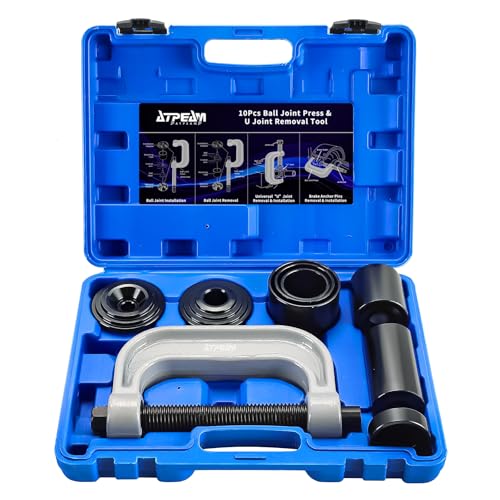
- Premium Quality: This ball joint tool kit is made of solid carbon steel with anti-rust finish, perfect for removal/installation of press-fit parts, such as ball joints, universal joint and truck brake anchor pins.
- Easy To Use: It will help you effortlessly remove press fit parts including ball joints, U-joints, brake anchor pins without removing the control arm from the vehicle. Besides, this tool kit can also remove rusted and corroded parts. Really save your energy and time in daily life.
- Package Included: 3x Receiving Tubes, 1x Removal Adapter, 1x Installation Adapter, 1x Screw, 1x Install Cup Adapter, 1x Forcing-screw Press, 1x Receiving Cup, 1x Installing Cup.
- Wide Application: The heavy duty 4-wheel drive ball joint tool is compatible with most American domestic and imported 2-wheel drive (2WD) and 4-wheel drive (4WD) cars. It allows service for 1/2 and 3/4 ton 4WD vehicles
- Blow Storage Case: The Ball Joint Press set is packed in a heavy-duty, storage case with precision-sized compartments for every piece - great for storage and transport while lengthening the life of the tool set.

- Gearwrench's Ball Joint Separator is made for separating the ball joint from the spindle support arm on domestic and import front wheel drive vehicles
- Adjustable for different size ball joints
- Suitable for most cars and light trucks (not intended for use on 3/4 ton or 1 ton trucks)
- Works on ball joints from 1-1/8” to 2-1/8” and 30 to 56mm in size
- Slot is 7/8" wide by 1-1/4" Deep


- 1, EASY OPERATION: The ORION MOTOR TECH Ball Joint Press Set with 4x4 Adapters effortlessly removes press-fit parts including ball joints, U-joints, brake anchor pins, and more on most 2-wheel drive (2WD) and 4-wheel drive (4WD) vehicles without removing the control arm.
- 2, UNIVERSAL COMPATIBILITY: Fits most American domestic and imported cars and light pickup trucks with press-fit type ball joints. Includes a 4WD adapter for service on 1967 - current 1/2 and 3/4 ton 4WD vehicles with the Dana 30 or 44 front axle (found on Ford, GM, Dodge, IHC, and Jeep vehicles).
- 3, PROFESSIONAL-GRADE DURABILITY: Constructed from heavy-duty forged steel with black-oxide finished adapters for maximum strength and longevity that resists rust and corrosion to endure years of heavy use.
- 4, ALL-IN-ONE TOOL SET: 3x Receiving Tubes, 1x Removal Adapter, 1x Installation Adapter, 1x Screw, 1x Install Cup Adapter, 1x Forcing-screw Press, 1x Receiving Cup, 1x Installing Cup.
- 5,PROTECTIVE CARRYING CASE: Each component is contained in a heavy-duty plastic carrying case with a handle for safe storage and quick organization. If you are not satisfied with this product or if you have any questions, please feel free to let us know.

- EASY OPERATION: Use the ORION MOTOR TECH Ball Joint Press Tool Set with 4WD Adapter to effortlessly remove press-fit parts including ball joints, U-joints, brake anchor pins, and more on most 2-wheel drive (2WD) and 4-wheel drive (4WD) vehicles without removing the control arm.
- UNIVERSAL COMPATIBILITY: Fits most American domestic and imported cars and light pickup trucks with press-fit type ball joints. Includes a 4WD adapter for service on 1967 - current 1/2 and 3/4 ton 4WD vehicles with the Dana 30 or 44 front axle (found on Ford, GM, Dodge, IHC, and Jeep vehicles).
- PROFESSIONAL-GRADE DURABILITY: Constructed from heavy-duty forged steel with black-oxide finished adapters for maximum strength and longevity that resists rust and corrosion to endure years of heavy use.
- ALL-IN-ONE TOOL KIT: 3x Receiving Tubes, 1x Removal Adapter, 1x Installation Adapter, 1x Screw, 1x Install Cup Adapter, 1x Forcing-screw Press, 1x Receiving Cup, 1x Installing Cup.
- PROTECTIVE CARRYING CASE: Each component is contained in a heavy-duty plastic carrying case with a handle for safe storage and quick organization.
This product presentation was made with AAWP plugin.